Get in Touch with TiAlloy Company


Quick Specs
| Construction | Corrosion-resistant cladding metallurgically bonded to a structural backing plate |
|---|---|
| Routes compared | Explosion bonding and hot-roll bonding |
| Core decision inputs | Service, layer duties, geometry, heat history, forming, welding, inspection, and traceability |
| Evidence stack | Material specification, construction code, project specification, order requirements, and plate-specific records |
Clad plate is primarily used when an engineered section requires two different metal duties: a process-side surface for corrosion behavior and a backing for structural duty. That distinction is often blurred because the term “clad” is used too broadly. This guide turns it into an engineering review sequence. This guide isn’t a substitute for the governing design code, corrosion study, welding procedure, or order-specific acceptance plan.
Clad plate combines a corrosion-resistant cladding layer with a structural backing through a metallurgical bond. Select it by service, layer duty, bonding route, fabrication sequence, and order-specific tests, not by alloy name or price alone.
TL;DR
- More heat isn’t automatically better for every bonded material system.
- The cladder, backer, and bond have separate duties that must be reviewed together.
- A passed plate test doesn’t prove later forming, welding, repair, or service performance.
- Check the commercial product page for current availability and quotation details; use this guide for engineering decision logic.
The routes considered for selected material systems include explosive bonding and the hot rolling process. The effect of welding enters later, when joint design and heat input can alter process-side performance. However, bonding strength, structural integrity, and temperature resistance must be kept apart in any layered design.
What Is a Clad Plate, and What Is It Not?
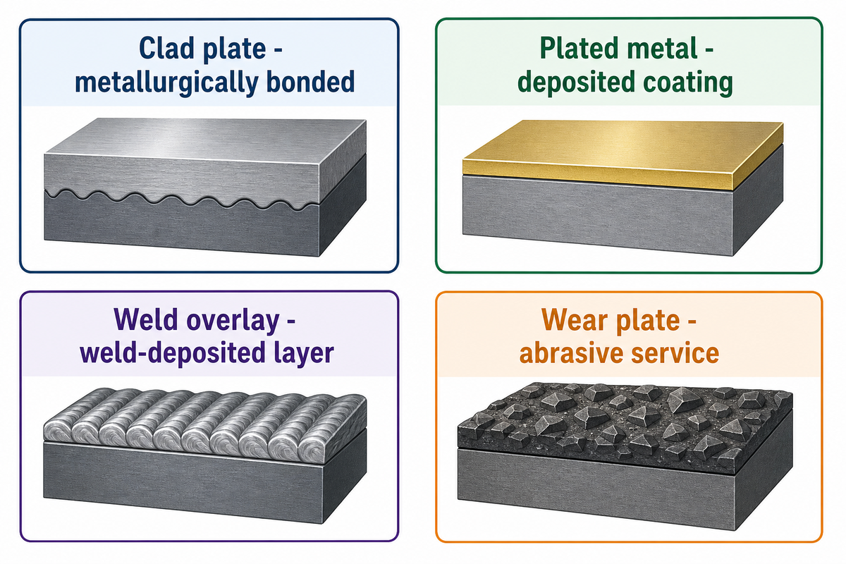
For the alloy-clad steel families discussed here, a clad plate is a composite metal plate in which a corrosion-resistant cladding layer is integrally and continuously bonded to a carbon- or low-alloy-steel base. ASTM public scopes separate chromium stainless, chromium-nickel stainless, and nickel or nickel-base alloy clad-steel families. That definition is important because it describes a bonded plate construction as opposed to a surface treatment, which has the same commercial nickname.
What’s the difference between clad and plated metal?
Clad metal describes a metallurgical bond between materials intended to share an engineered section. “Plated” describes a much thinner deposited coating, and weld overlay is deposited by welding and a wear plate is selected primarily for abrasion. Though these products can each be valid, they raise different design, inspection, fabrication, and repair questions.
| Product form | Primary construction idea | Question it must answer | Why it is not interchangeable |
|---|---|---|---|
| Clad plate | Metallurgically bonded cladder and backer | How will both layers and the bond perform? | Its interface is part of the engineering case. |
| Plated metal | Deposited surface coating | Will coating thickness and adhesion serve the exposure? | Coating behavior does not establish a load-sharing composite section. |
| Weld overlay | Weld-deposited corrosion-resistant layer | How are dilution, chemistry, and weld procedure controlled? | Deposition heat and overlay restoration become central. |
| Wear plate | Surface selected for abrasive service | What abrasive mechanism and impact duty apply? | Wear resistance is not a substitute for corrosion compatibility. |
Terms such as metal composite, steel composite, bimetallic plate, multi-layer product, and composite material are broad descriptions. None defines the governing specification. For carbon steel and stainless steel pairings, corrosion resistance of the stainless steel must be considered separately from the backing’s mechanical duty. Terms like mild steel and low-carbon steel aren’t exact material grades and conditions, and shouldn’t be relied upon for that purpose. Stainless steel cladding, for example, requires service-basis evaluation. As for welding of stainless steel, the actual joint requires qualification.
To begin, naming the construction and service-side threats is critical. A drawing that only says “clad” is ambiguous and could mean corrosion fluid, abrasion, a repair layer, or a bonded structural product. This ambiguity could lead to the wrong test plan prior to even discussing a material grade.
The 3-Layer Duty Triangle: Cladder, Backer, and Bond
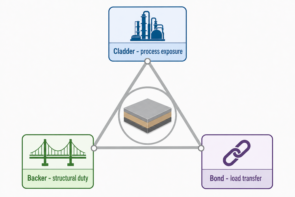
The 3-Layer Duty Triangle is a functional model, not a physical model. A one or two-sided cladding can create different arrangements of interface. The “three” refers to three linked questions: what faces the process, what carries the main design duty, and what transfers stress between them.
“integrally and continuously bonded on one or both sides”
| Duty | Primary question | Evidence to request | Consequence of a wrong assumption |
|---|---|---|---|
| Cladder | What chemical, temperature, and flow exposure reaches the surface? | Corrosion basis, fluid description, temperature envelope | A compatible-looking grade may be unsuitable in the actual environment. |
| Backer | What load, thickness, and design-code duty does the substrate carry? | Design basis and material specification | Corrosion resistance may be mistaken for structural capacity. |
| Bond | How will load transfer survive fabrication and service? | Bond-test intent, inspection plan, forming and welding review | A plate-level result may be overextended to the finished component. |
Carbon steel is considered for the backer because it can provide high strength and structural support while a more corrosion-resistant clad layer faces the process fluid. This is role assignment and not a material recommendation. Chemical composition, pressure duty, temperature, weld joint details, and fabrication sequence can change the suitable pair in chemical industry equipment.
Explosion Bonding and Roll Bonding: Route Constraints
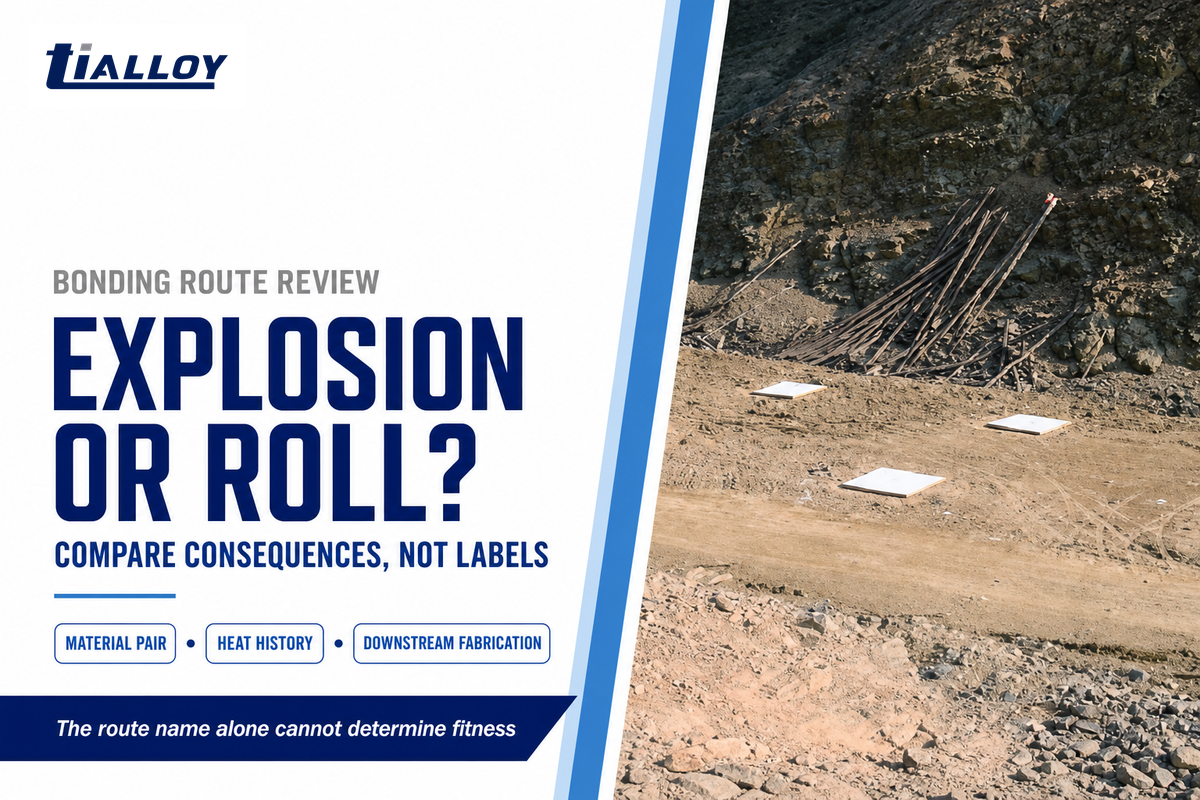
Explosion bonding and roll bonding should be compared through the material pair, geometry, heat history, downstream forming, welding plan, and required evidence. The route name alone can’t determine fitness. A valid selection connects the interface made at the plate mill to all downstream operations on the finished component.
How should I choose between explosion-bonded and roll-bonded plate?
Adequate selection requires review of material pair, starting geometry, thermal history, forming route, welding plan, and acceptance evidence. Neither explosion bonding nor hot-roll bonding is an absolute winner. Both can produce a usable clad steel plate only when the interface, downstream fabrication, and order requirements match the actual materials and component.
Published work on bonded metal systems shows why route names alone are weak decision criteria: interface phases and mechanical properties can change with material pair and heat history. A route assessment must determine not only how a bond is effected, but what subsequent thermal exposures, forming strains, arc welding, and inspection considerations the route must endure.
The descriptions given for the mechanical properties of stainless steel don’t cover the entire bonded section. Research may compare bonding properties and interfacial morphologies while production planning has to take into account the actual reduction and heat path. Explosive bonding and metal arc welding occur at different stages, so evidence for one can’t substitute for control of the other. A phrase like hot rolled stainless steel clad may suggest a route family, but doesn’t define a complete order. Rolled stainless steel clad plates may differ in grade, backing, dimensions, heat treatment, test scope and acceptance basis.
Explosion bonding review
- Examine material-pair compatibility and interface design.
- Confirm geometry and later forming constraints.
- Review any staged processing or intermediate-layer rationale.
Hot-roll bonding review
- Examine surface preparation and reduction path.
- Track heat history and post-bond thermal exposure.
- Review interface evidence for the actual material system.
A practical route brief should state the cladder, backer, intended component geometry, maximum planned thermal exposure, forming locations, welding sequence, required inspection coverage, and who approves deviations. This is a more productive approach than an open request to the “strongest” bonding method because it brings the consequences downstream into focus.
When Does Clad Plate Beat Solid Alloy?
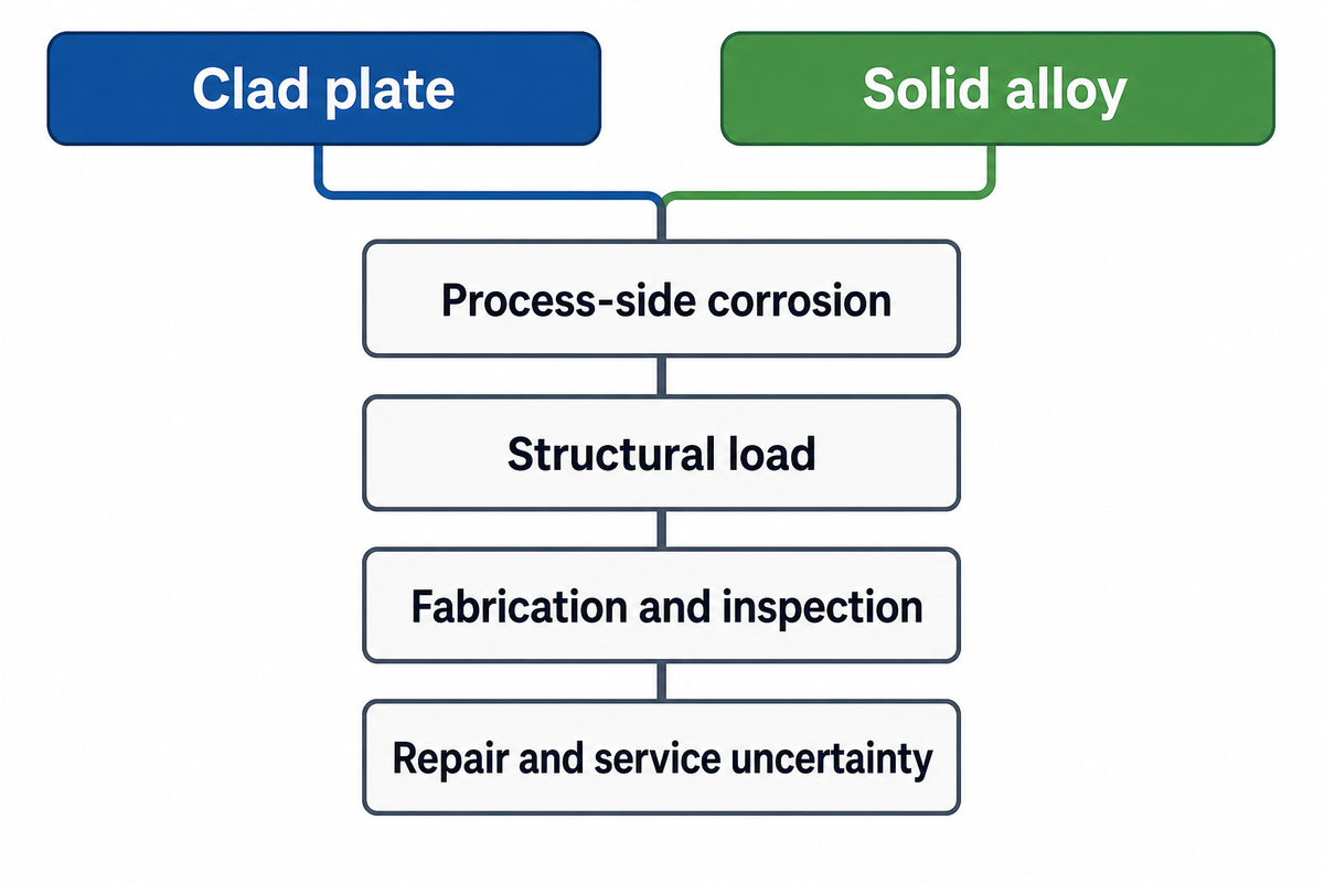
Compare clad plate with solid alloy when the process side needs corrosion resistance but the load-bearing section does not require the same expensive alloy throughout. A 2024 peer-reviewed review of laminated metal composites treats material pairing, interface behavior, processing, and joining as linked constraints rather than a universal cost formula. The project basis also includes forming, weldability, inspection, repair access, schedule risk, and service consequence.
| Decision factor | Condition that can favor clad plate | Condition that can favor solid alloy | Evidence owner |
|---|---|---|---|
| Process-side corrosion | Surface duty can be met by a qualified cladder | Whole section must resist the environment | Corrosion engineer |
| Structural load | Backer can carry the specified load | Alloy properties are required through thickness | Design engineer |
| Geometry | Plate can be formed within qualified limits | Complex shapes make a bonded interface difficult to control | Fabrication engineer |
| Welding | Joint and restoration details are qualified | Clad-edge and dilution controls add disproportionate complexity | Welding engineer |
| Inspection | Bond and finished-component checks are defined | Required coverage cannot be achieved or interpreted clearly | Quality lead |
| Repair | Repair procedure preserves intended surface and interface duty | Repair access or requalification is impractical | Owner engineer |
| Schedule | Qualification and evidence can be completed in the project window | Interface review adds an unacceptable critical-path risk | Project manager |
| Service uncertainty | Fluid, temperature, and transients are sufficiently characterized | Unknown exposure makes conservative whole-section selection necessary | Process owner |
| Documentation | Plate identity and test records can follow the component | Traceability cannot be maintained across fabrication | Quality system owner |
A claim of percentage savings shouldn’t be substituted for this comparison. A lower alloy volume may be attractive, but no general break-even, service-life multiplier, or price outcome can be inferred without the actual design and fabrication basis.
Material Pairing by Service Condition and Application
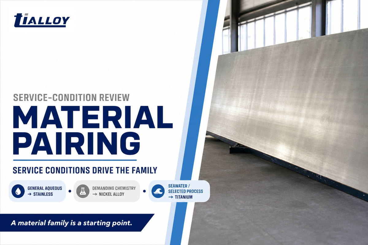
Material-family tables are starting points for a corrosion and fabrication review, not grade-selection tools. The process stream, impurities, pressure, temperature, crevices, cleanability, and shutdown exposure determine whether a material family remains viable. Planned welding conditions determine whether a material family remains viable. The linked product pages below provide navigation to material families. These pages do not establish suitability for a particular service.
| Service or application question | Possible cladder family to examine | Why it may enter the review | Confirmation still needed |
|---|---|---|---|
| General aqueous corrosion duty | Stainless steel plate | Stainless families are commonly reviewed for corrosion resistance. | Chlorides, temperature, pH, and fabrication condition. |
| Grade-specific stainless question | 316L corrosion and verification guide | It provides grade-focused context. | Whether 316L is compatible with the actual medium and weld condition. |
| More demanding chemical exposure | Nickel alloy materials | Nickel-base alloys may be considered where service calls for their corrosion behavior. | Exact chemistry, temperature, and code requirements. |
| Seawater or selected process duty | Titanium plate and sheet | Titanium materials may enter a service-specific review. | Crevice, galvanic, temperature, and fabrication boundaries. |
| Heat exchanger channel or shell component | Stainless, nickel alloy, or titanium family | Different sides may face different fluids. | Both fluid circuits, design pressure, and tube-to-sheet details. |
| Petrochemical process equipment | Stainless or nickel-alloy family | Corrosion and temperature can govern the exposed layer. | Contaminants, sour-service factors, and welding procedure. |
| Pressure vessels | Service-selected cladder over structural backer | Roles can be separated within the plate construction. | Construction code, design basis, and qualified fabrication. |
| Condensers or desalination equipment | Titanium or other service-selected family | Water chemistry and crevice behavior can be decisive. | Water analysis, flow, deposits, and galvanic interfaces. |
| High-temperature process service | Material pair selected by exposure | Interfacial diffusion and thermal history can matter. | Time at temperature, transients, and post-weld treatment. |
| Mixed or changing media | No family should be assumed adequate | Variation can defeat a narrow compatibility assumption. | Complete operating envelope and upset conditions. |
Before large-scale application in petroleum or chemical industry equipment, the owner still needs a defined operating envelope and corrosion review. The petrochemical industry is too broad a label to select a cladder. Finite element analysis can aid a geometry-specific stress review, but shouldn’t be relied on to determine fluid compatibility. Studies of interfacial characteristics and element diffusion are useful only when the researched material stack and heat history match the decision being made.
For instance, “stainless steel clad plate” is a broad product label, but it does not determine whether an austenitic, duplex stainless steel, nickel, or titanium cladding metal is appropriate. Have the corrosion reviewer relate each option to the entire service envelope and the planned fabrication route.
Standards and Tests: An Evidence Hierarchy
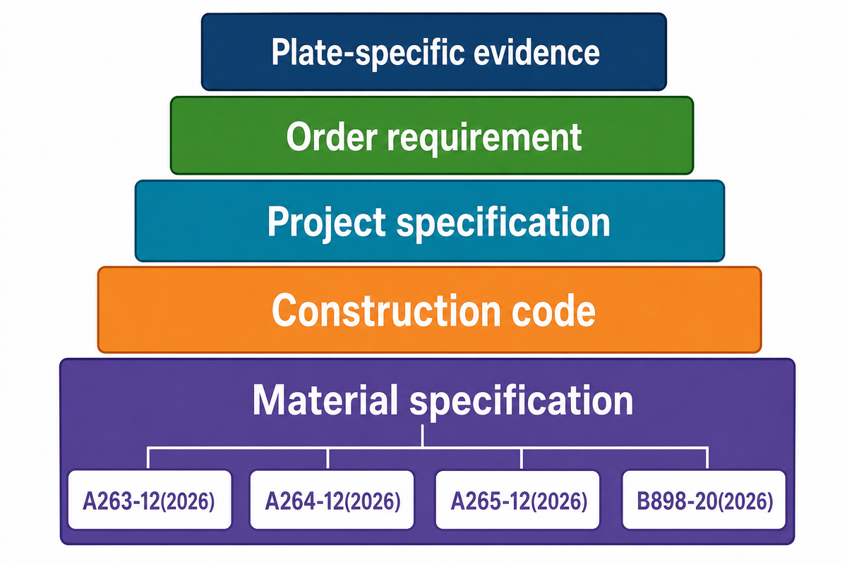
Standards, construction-code requirements, order requirements, and plate-specific records should form a layered evidence system; a single certificate is not a substitute. Separate the product specification from the construction code, project specification, purchase-order requirements, and plate-specific records. Each addresses a different concern regarding material identification, fabrication control, inspection, and final acceptance.
Which material, thickness, bond tests, and documents should be defined before ordering?
Determine the service condition and requirements, define layers, dimensions, the governing material specification, construction code path, fabrication constraints, test intent, and evidence linkage before placing an order. Material standards and pressure equipment rules are different but related. The final acceptance plan must identify the actual plate, the test object, timing, procedure, coverage, and decision authority.
ASTM public webpages identify A263-12(2026), A264-12(2026), and A265-12(2026) as active specifications for distinct alloy-clad steel families. Their public scopes support the classification and bonded construction concept. They do not publish a universal acceptance value that safely applies to all material pairs, thicknesses, and projects.
The current ASTM B898 family page lists B898-20(2026) as Active for clad plate involving titanium, zirconium, tantalum, niobium, and their alloys on a base metal. An older version-specific B898 page may be historical; that does not speak to the status of the family page. Use the controlled copy purchased for the job, not a web page label by itself.
- Material specification: identifies the product family, material scope, and referenced test categories.
- Construction code: governs the completed pressure component or other equipment in its intended application.
- Project specification: connects service, geometry, fabrication, inspection, and documentation to the job.
- Order requirement: states which tests, coverage, acceptance basis, and documents are required for this plate.
- Plate-specific evidence: links the actual material and results to the actual order.
| Evidence or test | What it can establish | What it cannot establish alone | Question to put in the order |
|---|---|---|---|
| Chemical analysis | Reported chemistry for the identified material or location | Bond continuity or finished weld performance | Which layer, location, and method apply? |
| Base-metal tensile result | Mechanical result for the tested base material | Finished bond performance if testing preceded cladding | Was this test before or after cladding? |
| Bond or shear test | Specified bond behavior on the required test object | All later forming, weld, and service outcomes | Is it required, where is it sampled, and what governs acceptance? |
| Bend test | Response of the tested coupon under the stated bend method | Full-component geometry tolerance | Which direction, radius, and acceptance basis apply? |
| Ultrasonic inspection | Reportable unbonded areas under the selected procedure and coverage | Cladding chemistry, corrosion resistance, or future weld quality | What scan coverage, calibration, map, and criteria are required? |
| Material certificate | Listed heat, lot, chemistry, and results linked by documentation | Proof that every order-specific bond or fabrication requirement is met | How will the certificate link to plate identity and release? |
One material specification can cover mechanical properties and corrosion resistance without making one result proof of the other. Tensile strength and yield strength belong to a stated specimen and condition. A ductile bend response can be relevant evidence, but can’t replace the specified bond examination or acceptance decision.
The difference is sequence. A base-metal tensile report and a specified bond or shear test concern different test objects; the governing specification and order define the applicable testing and acceptance trigger. The record must state what was tested, when it was tested, and the reason it was required.
Where Clad Plate Fails: Interface, Forming, Welding, and Service
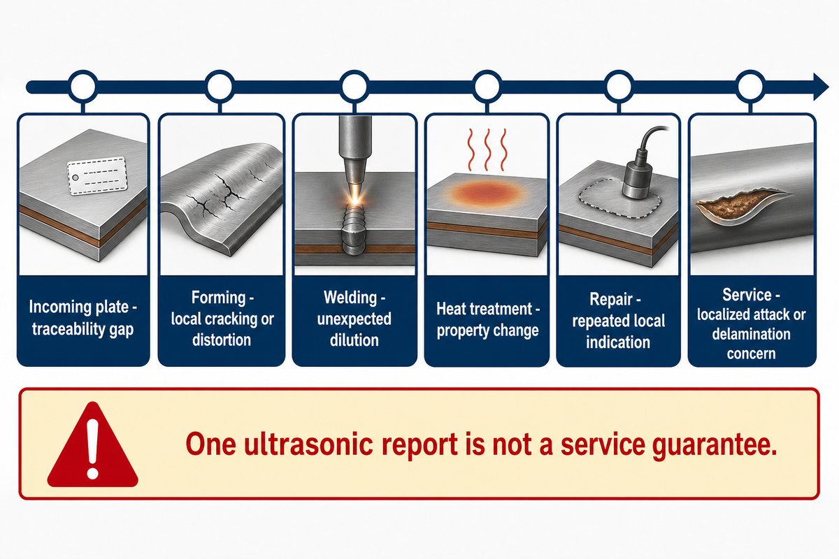
Clad plate failures should be investigated by stage, not diagnosed from one photograph or a single test result. A bond may be satisfactory on a plate coupon yet a later forming operation, welding sequence, thermal treatment, repair, or service exposure can introduce a different risk. The 2024 metallurgy review and an Oak Ridge National Laboratory fabrication survey illustrate remote diagnosis isn’t an engineering release decision.
A technical analysis could compare microstructure and mechanical properties with recorded thermal and fabrication histories. A scanning electron microscope and fractography can help characterize a selected specimen, but neither method can conclusively prove the condition of an unexamined component. Investigators may also verify whether local zones are decarburized or carburized and whether austenite transformation matters for the specific alloy system. Stress-strain curves, interfacial shear strength, and ductile behavior must be tied to their specimen, orientation, and test condition.
Do
- Trace the signal to its life-cycle stage.
- Preserve plate identity and fabrication records.
- Review weld and heat history before disposition.
Don’t
- Call one ultrasonic report a service guarantee.
- Assume more heat improves every interface.
- Diagnose delamination without a qualified investigation.
| Stage | Signal | Possible mechanism | Evidence needed next | Next decision |
|---|---|---|---|---|
| Incoming plate | Traceability gap | Material and report cannot be linked | Plate marking, certificate, receiving record | Hold until identity is established |
| Incoming plate | Mapped unbonded indication | Bond discontinuity within stated inspection scope | UT procedure, calibration, coverage map, acceptance basis | Escalate to order-specific disposition |
| Cutting | Edge separation or damage | Cutting detail exposes or affects the interface | Cut plan, edge condition, procedure review | Define edge treatment or repair review |
| Forming | Local cracking or distortion | Strain path exceeds qualified behavior | Forming radius, direction, strain history, inspection | Review qualification and geometry |
| Welding preparation | Clad-edge mixing risk | Joint design allows unintended interaction | Joint drawing, bevel detail, WPS | Revise sequence or consumable plan |
| Welding | Unexpected dilution | Heat input or filler sequence alters deposited chemistry | WPS, heat input record, chemistry verification as required | Assess corrosion-side restoration |
| Welding | Cracking near transition | Residual stress, restraint, hydrogen, or incompatible procedure | Weld records, NDE, material and service review | Qualified failure investigation |
| Heat treatment | Property change after exposure | Diffusion or phase change in the specific system | Time-temperature record and material-pair evidence | Confirm thermal cycle acceptability |
| Inspection | Incomplete coverage | Test result leaves an unexamined region | Coverage map, access constraints, procedure | Decide whether supplemental examination is needed |
| Repair | Repeated local indication | Repair route does not address underlying mechanism | Repair history, dimensions, approval record | Stop repetitive repair and reassess cause |
| Commissioning | Early leak or corrosion signal | Service condition differs from design assumption | Fluid data, location, operating history | Contain and investigate under owner procedure |
| Service | Localized attack or delamination concern | Corrosion, mechanical loading, thermal cycling, or fabrication interaction | Inspection findings, metallurgical review, service data | Qualified fitness-for-service decision |
A 2024 TA2/DT4/Q235B study reported shear strength of 184.5 MPa in its as-rolled specimen, 195.4 MPa after a 550 °C, 2 h anneal, and a decrease at 650 °C. These values belong to that tested material stack and thermal program, not to an order acceptance limit. Their practical lesson is that more heat isn’t automatically better.
Clad Plate Decisions: 10 Consequence Checks
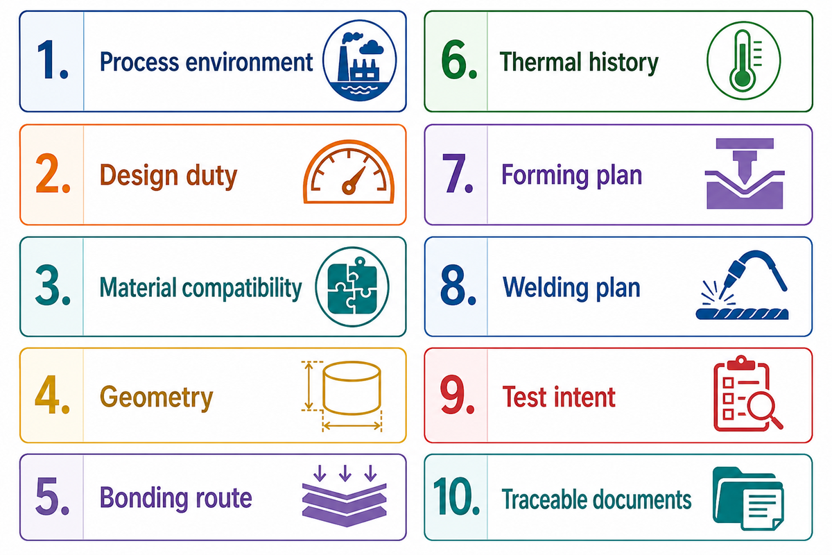
The named framework below is for a cross-functional review. A 2024 review of metal-clad plate interfaces and joining identifies risks that span oxide-contaminated interfaces, carbon migration, weld dilution, residual stress, and repeated thermal cycles. Each answer can change the material pair, bonding method, test plan, or fabrication sequence. If an answer is unknown, uncertainty should be captured rather than guessing with an answer that’s assumed to be correct.
| Check | Why it matters | What can change | If unknown |
|---|---|---|---|
| 1. Process environment | Defines corrosion-side duty | Cladder family and corrosion review | Do not freeze material selection |
| 2. Design duty | Defines structural responsibility | Backer, total section, code route | Hold the structural basis open |
| 3. Material compatibility | Interface behavior is system-specific | Pairing, intermediate design, route review | Request technical review |
| 4. Geometry | Shapes determine strain and access | Plate formability, joint details, inspection access | Model the component before procurement |
| 5. Bonding route | Route sets interface and heat-history questions | Qualification evidence and process controls | Compare consequences, not labels |
| 6. Thermal history | Heat can alter an interface | Post-bond treatment and welding sequence | Define the maximum intended cycle |
| 7. Forming plan | Local strain can become a bond risk | Radius, direction, qualification, inspection | Obtain fabrication input |
| 8. Welding plan | Dilution and restoration affect the process side | WPS, filler metals, sequence, NDE | Do not assume standard steel practice applies |
| 9. Test intent | Different tests answer different questions | Sampling, timing, coverage, acceptance basis | Write the decision question first |
| 10. Traceable documents | Evidence must follow the plate to the component | Marking, certificates, maps, release package | Assign a documentation owner |
These checks are purposefully consequence-based. It’s important to not lose the consequence in a requirement by representing it as a passive list of fields. For example, in forming total thickness affects structural calculations, forming, weld prep, inspection access, and the relationship between base metal and clad layer.
How to Define a Clad Plate Requirement Without Duplicating a Supplier RFQ
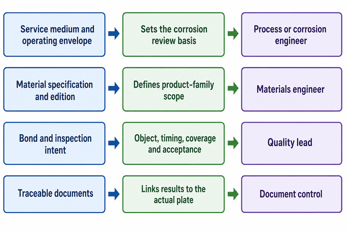
Requirements are to be written by explaining consequences behind inputs without rephrasing or redefining a catalog, published range table, or quote checklist. The public ASTM A263 scope and testing summary illustrates why a requirement must distinguish the product family, base-metal test object, and order-triggered bond evidence instead of naming clad plate alone. An input requirement begins with the intended component and service. Then document the layer duties, drawing dimensions, material specification, construction-code route, fabrication limits, inspection intent, and documents that must remain traceable to the plate.
| Requirement field | Engineering consequence | Accountable owner |
|---|---|---|
| Service medium and operating envelope | Sets the corrosion review basis | Process or corrosion engineer |
| Cladder and backer duties | Separates process-side and structural roles | Design engineer |
| Dimensions and final geometry | Sets forming and inspection constraints | Mechanical designer |
| Material specification and edition | Defines product-family scope and controlled reference | Materials engineer |
| Construction-code route | Connects plate to equipment compliance | Code engineer |
| Bond and inspection intent | Defines object, timing, coverage, and acceptance basis | Quality lead |
| Forming and welding constraints | Protects the interface through fabrication | Fabrication and welding engineers |
| Traceable documents | Links results to the actual plate and component | Document control |
This document provides an engineering basis to a supplier. A field list does not establish commercial availability. This also allows a buyer to recognize missing decisions before they turn into late order clarifications.
How to Evaluate a Clad Plate Supplier’s Evidence
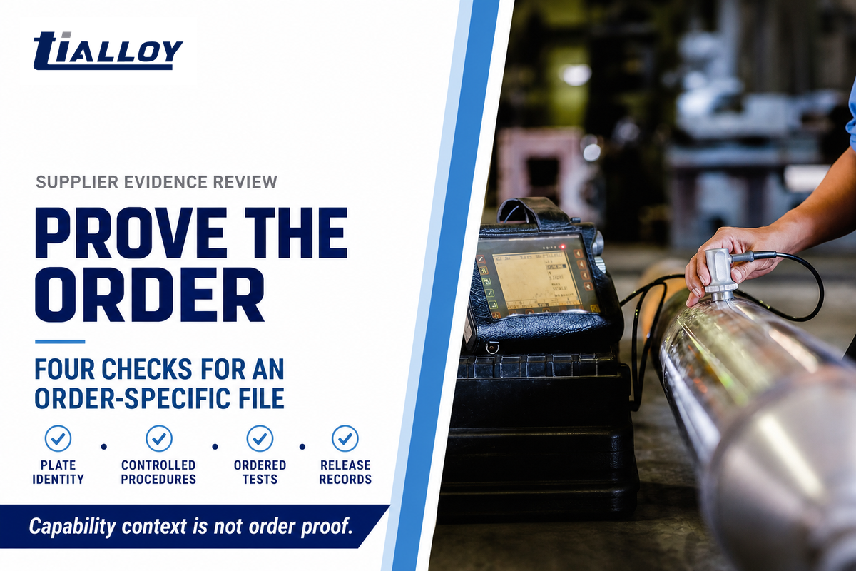
Evaluate what the evidence proves, not how prominently the supplier markets it. It’s important to identify what’s described in the evidence, who controlled the process and test, what plate identity appears on the evidence, and if the evidence addresses the requirement. A generic certificate or broad capability statement is not an order-specific release package.
TiAlloy reports more than 20 years of metal manufacturing experience, a 30,000-square-meter production facility, ISO 9001, and occupational health and safety management. Its published company background also lists MTC / EN 10204 3.1, PMI, UT, mechanical testing, corrosion testing, dimensional tolerance, surface quality, batch traceability, and export packing as capabilities. These are first-party company facts, not independent proof for a particular order or a promise that every plate includes every listed test or document. Ask for the current certificate scope and order specific records. See TiAlloy quality and manufacturing background for that company context.
For a particular job, ask the supplier to connect the provided plate to the governing specification, controlled procedures, ordered tests, inspection, nonconformance, and final traceability package. Once the engineering basis is defined, review clad plate material options and order requirements for appropriate commercial handoff.
What Is Changing, and What Is Not in Clad Plate Selection?
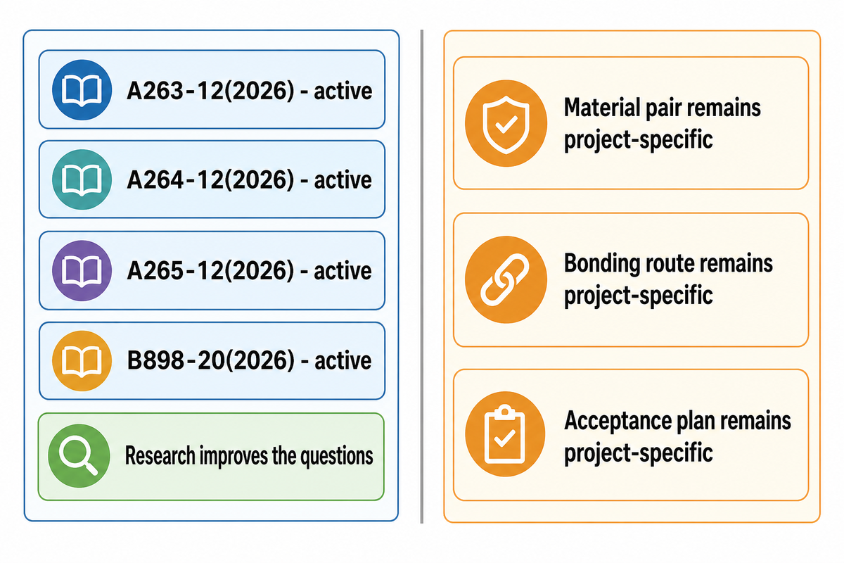
As checked on 8 October 2026, ASTM public pages list A263-12(2026), A264-12(2026), and A265-12(2026) as active, while the current B898 family page lists B898-20(2026) as Active. While edition currency is good evidence, it does not create a universal material pair, bonding route, or acceptance plan.
Recent interface research can improve the questions asked about microstructure, diffusion, mechanical properties, and heat treatment. It doesn’t remove the duty to verify the actual material system and final fabrication route. Treat updated standards and studies as a reason to check the evidence hierarchy, not as a shortcut around project-specific engineering review.
Key takeaway
A sound clad-plate decision links service, layer duties, bonding route, fabrication, test object, timing, order trigger, and traceable records before a material name becomes a purchase decision.
Frequently Asked Questions
What is stainless clad?
Stainless clad is a layered product in which stainless steel is metallurgically bonded to a backing plate, usually carbon or low-alloy steel.
Its stainless layer supplies the intended process-side corrosion resistance while the backing commonly carries much of the structural duty. That division of duties does not make every stainless grade suitable for every fluid or temperature. The project still needs a corrosion basis, layer definition, bonding-route review, required tests, fabrication controls, and a traceable acceptance plan for the actual component.
How does clad plate work?
Clad plate works by assigning different engineering duties to a cladding layer, a backing layer, and their bonded interface.
The cladding faces the process environment, the backing provides the principal structural section, and the interface transfers load between them. This can reduce the amount of high-alloy metal needed in an engineered section, but it also creates interface, forming, welding, inspection, and repair questions. The material pair is only one input; the finished equipment depends on how all of those duties are controlled together.
Are clad plates safe for pressure equipment?
Clad plate can suit pressure equipment when the material specification, design code, fabrication procedure, inspection plan, and acceptance records apply to the actual component.
The word clad proves none of those conditions by itself. A plate certificate, bond test, or ultrasonic report can contribute to the evidence package, but each has a defined object and scope. Qualified project engineers must review the construction-code route, process conditions, material pairing, geometry, welding details, examination coverage, and final release records for the vessel or exchanger being built.
Can titanium be bonded to carbon steel?
Titanium-to-steel clad plate can be produced for suitable projects through a solid-state bonding route.
Compatibility, any required intermediate design, dimensions, heat history, later forming, welding details, tests, and service conditions must be reviewed for the specific order. A historical process example or product-family scope is not proof that a route is current, available, economical, or suitable for a present design.
What does ultrasonic bond inspection prove?
Ultrasonic inspection can identify reportable unbonded areas under the selected procedure, scanning coverage, and acceptance rules.
It does not independently establish cladding chemistry, shear performance, forming tolerance, weld quality, corrosion resistance, or fitness for the completed equipment. Read the report with its technique, calibration, coverage map, plate identity, and acceptance basis. It cannot predict damage introduced later by forming, welding, heat treatment, repair, or service exposure.
Which side faces the process fluid?
The corrosion-resistant cladding normally faces the process fluid while the backing plate supplies structural support.
Normally, the cladding faces the process fluid and the backing carries structural duty. Confirm the final orientation on the approved drawing.
Does a material certificate prove bond quality?
No, a material certificate alone does not prove every aspect of bond quality for the finished component.
A certificate may document identified materials, chemistry, mechanical results, heat or lot traceability, and listed tests, but its value depends on scope and linkage to the plate. Bond quality may also need ultrasonic, shear, bend, or other order-specific evidence. Review document number, plate identity, test location, method, acceptance basis, results, deviations, and authorized release.
Project-specific engineering review
Use the guide to prepare the service, layer-duty, fabrication, inspection, and documentation questions. TiAlloy can then review the commercial material options against that engineering basis.
This guide is purely educational. It doesn’t substitute the controlled edition standard, corrosion assessment, construction code, qualified fabrication procedures, and approval of responsible project engineers. Company facts are identified separately from independent technical sources.
Related Articles
References & Sources
- ASTM A263-12(2026), public scope and status page.
- ASTM A264-12(2026), public scope and status page.
- ASTM A265-12(2026), public scope and status page.
- ASTM B898 family page, public scope and current status.
- ASME Section VIII, Division 1 overview.
- Oak Ridge National Laboratory survey of cladded-component fabrication practices.
- Materials (2024), review of production and welding issues in clad steels.
- Coatings (2024), TA2/DT4/Q235B vacuum hot-rolling and annealing study.
- TiAlloy About Us first-party quality and documentation page, including MTC / EN 10204 3.1 capability when required.